


 Domicile /
Why a Gear Reduction Motor Fails After Installation: 7 Mismatch Causes to Check Before Blaming the Gearbox
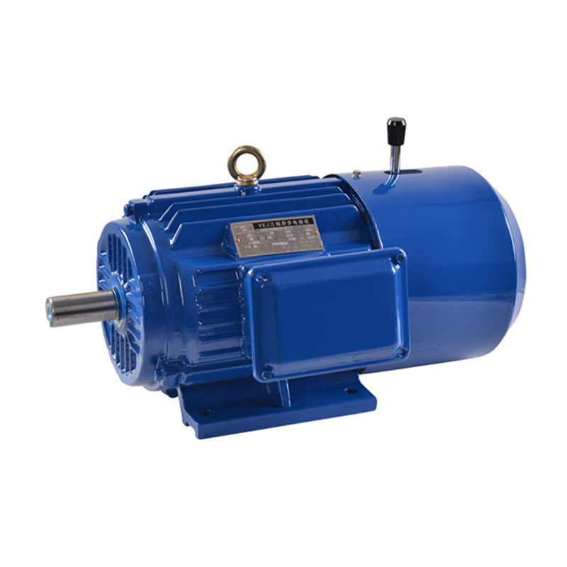
Entraînements à axe vertical après perte de puissance: Quelles données de retenue et de freinage doivent être vérifiées par les fabricants?
14 octobre, 2026
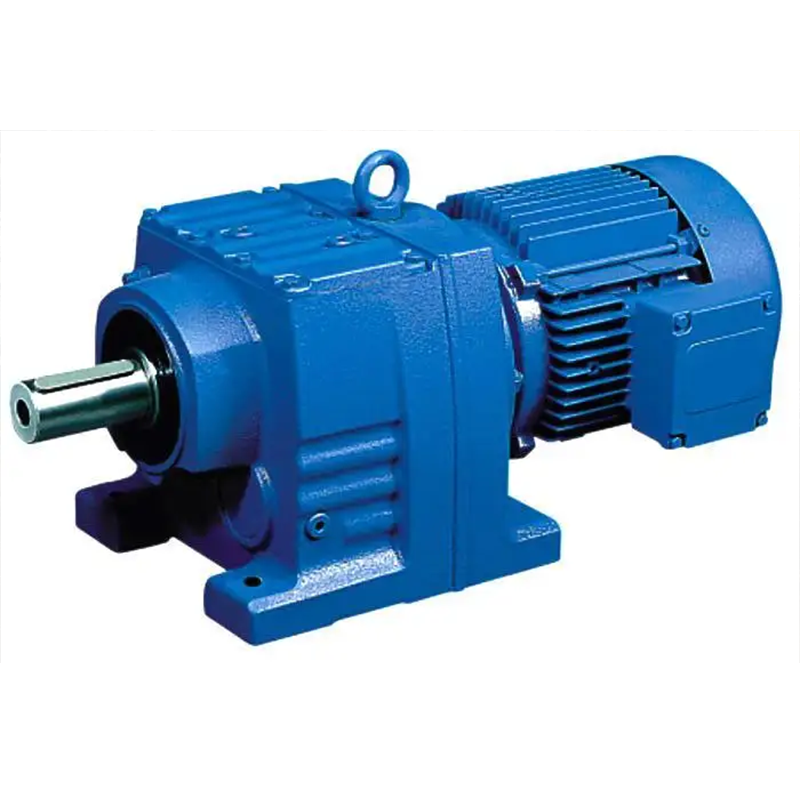
Machines d’indexation d’emballage: Calcul du couple d’accélération à partir d’un profil de mouvement
14 octobre, 2026
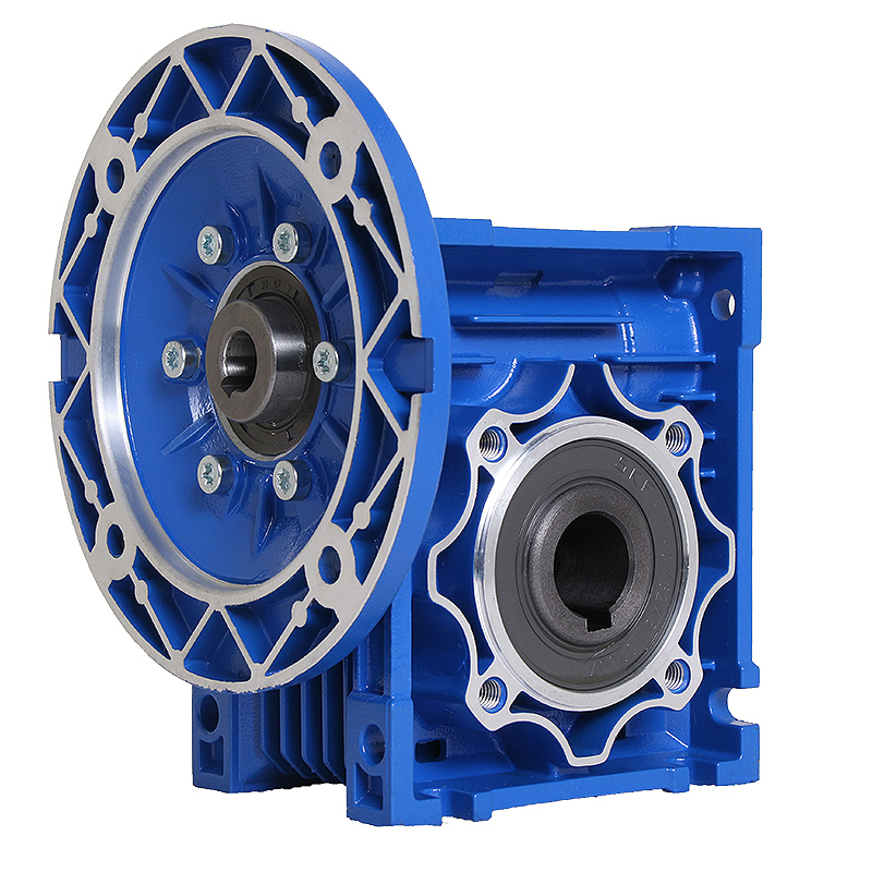
Changement du rapport de boîte de vitesses à vis sans fin NMRV: Peux-tu garder le moteur existant?
14 octobre, 2026
Comment vérifier la charge en surplomb lorsqu’un pignon à chaîne est déplacé le long d’un arbre de sortie de boîte de vitesses
14 octobre, 2026
A gear reduction motor is installed on a new mixer. The ratio is correct, the motor power matches the specification, and the mounting bolts line up. The unit runs for three weeks — then the bearings fail, the seals leak, and the gearbox is covered in oil. The first call is to the supplier: “Your gearbox is defective.”
Maybe it is. But maybe it is not.
Gearbox failures that occur shortly after installation are often caused by application mismatches rather than manufacturing defects. The gearbox was correctly manufactured, but it was specified, installed, or operated in a way that exceeded its design limits. Distinguishing between a manufacturing defect and an application mismatch requires evidence — not assumption. This article provides a framework for investigating early failures, covering seven categories of mismatch that should be checked before attributing the failure to product quality.
Manufacturing Defect vs. Application Mismatch: Two Different Causes
Before examining the seven mismatch categories, it is important to acknowledge that both manufacturing defects and application mismatches are real possibilities. A fair investigation considers both:
Manufacturing defects include:
- Material defects (inclusions, hardness variations, incorrect heat treatment)
- Machining errors (incorrect gear geometry, bore dimensions, tooth spacing)
- Assembly errors (incorrect bearing preload, misaligned gear positions, missing or incorrect lubricant at the factory)
- Design errors (inadequate gear geometry for the rated load, undersized bearings)
Application mismatches include:
- Selection errors (wrong ratio, wrong service factor, wrong duty type)
- Installation errors (shaft misalignment, incorrect mounting, wrong oil level)
- Operating condition changes (load increase, duty cycle change, environment change)
- Maintenance neglect (oil not changed, breather blocked, seals not inspected)

Both categories can produce the same symptoms: Bruit, heat, Vibration, Fuite, and eventual failure. The difference is in the evidence — and a systematic investigation should collect the evidence before assigning blame.
Mismatch 1: Ratio or Output Speed Mismatch
Que se passe-t-il
The gear ratio does not match the application requirement. The output speed is too fast or too slow for the driven process.
Failure Mechanism
- Output too fast: The driven equipment runs above its design speed. If the load torque increases with speed (as in fans, Pompes, and some conveyors), the motor is overloaded — drawing above rated current and overheating. The gearbox transmits more torque than it was selected for, accelerating gear and bearing fatigue.
- Output too slow: The motor runs below its optimal speed range. If a VFD is used to compensate by increasing the motor speed, the motor may operate outside its efficient range. If the motor is an AC induction motor running at a lower speed due to a higher ratio, the cooling fan output is reduced (the fan spins at motor speed, not output speed).
Evidence to Collect
- Measure the actual output RPM and compare to the required speed
- Check the motor current under load — is it above or below the rated value?
- Check the motor speed (if a VFD is used, read the output frequency and calculate the expected motor speed)
- Verify the ratio on the nameplate against the original specification
Mismatch 2: Torque or Service Factor Insufficient
If the ratio and speed are correct, the next category to investigate is whether the gearbox is mechanically adequate for the actual load.
Gear motor failed after installation? Before blaming the gearbox, check whether the selection matched the actual load. Send the failure mode, Heures d’ouverture, load description, and nameplate data — we can help determine whether the failure is a selection issue, an installation issue, or a product issue.
Que se passe-t-il
The gearbox is mechanically overloaded — the actual load torque exceeds the gearbox’s rated output torque, or the service factor applied during selection was too low for the actual operating conditions.
Failure Mechanism
- Continuous overload: The gear teeth experience stress above their design limit continuously. Surface fatigue (pitting) develops on the tooth flanks. Bending fatigue progresses at the tooth root. Over time, the teeth pit, spall, or fracture.
- Shock overload: A single shock event (material jam, sudden load increase) exceeds the gear tooth strength and causes immediate fracture — even if the continuous load is within rating.
- Inadequate service factor: The selection was based on nominal load without accounting for shock, frequent starts, or long operating hours. The gearbox is technically rated for the nominal torque but not for the actual severity of the application.
Evidence to Collect
- Inspect the gear teeth: pitting can be associated with repeated contact stress, lubrication condition, contamination or other factors; tooth fracture can be associated with overload or impact, but material, heat-treatment, alignment and manufacturing factors should also be considered
- Check the application’s actual load class (uniform, moderate shock, heavy shock) against the service factor used for selection
- Review the operating hours and start frequency — have they increased since the original selection?
Mismatch 3: Shock Load, Frequent Starts, or Reversing Not Accounted For
If the torque rating is adequate, the next question is whether the operating conditions — shock, starts, reversing — were communicated during selection.
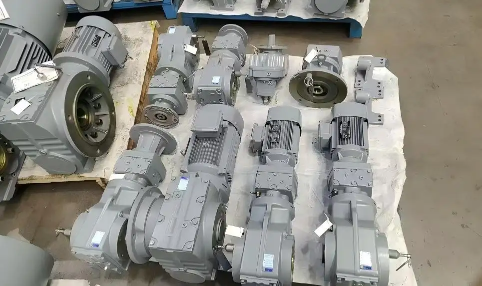
Que se passe-t-il
The application has operating conditions (shock loads, frequent starts, reversing) that were not communicated during selection. The gearbox was selected for uniform load and occasional starts, but the actual application is more severe.
Failure Mechanism
- Frequent starts: Each start introduces a torque transient (the motor must accelerate the load from rest). Frequent starts fatigue the gear teeth and bearings through repeated stress cycling. If the start current significantly affects temperature (S4 duty), the motor windings also experience thermal cycling that accelerates insulation aging.
- Shock loads: Sudden load spikes (material entering a crusher, a jam in a conveyor) impose momentary torque that may exceed the gear tooth strength. Even if the continuous load is within rating, repeated shock events cause cumulative fatigue.
- Reversing: Each direction change transfers the load from one face of the gear tooth to the other, with an impact load during the transition (as the backlash is taken up). Frequent reversing accelerates tooth surface wear and can cause tooth tip damage.
Evidence to Collect
- Record the actual starts per hour and compare to the selection specification
- Check for shock load events (material jams, sudden load changes) in the process log
- Inspect the gear teeth for impact damage (chipped tooth tips, localized pitting on one face)
- If reversing, inspect both faces of the gear teeth for wear
Mismatch 4: Shaft Alignment, Overhung Load, or Radial Load Exceeded
If the selection parameters check out, the next area to investigate is the installation itself — specifically the mechanical forces on the output shaft.
Que se passe-t-il
The output shaft is subjected to forces it was not designed to handle — from misalignment between the gearbox and driven shaft, from excessive chain or belt tension on a sprocket or pulley, or from a radial load that exceeds the bearing capacity.
Failure Mechanism
Shaft misalignment and excessive overhung load are among the most common causes of premature bearing and seal failure.
- Misalignment: When the gearbox output shaft and the driven shaft are not aligned (radially or angularly), the coupling transmits bending forces to the shaft. These forces load the output bearing unevenly, causing localized wear, Surchauffe, and eventual bearing failure. The shaft itself may fatigue from the cyclic bending stress.
- Overhung load: A sprocket, Poulie, or chain mounted on the output shaft creates a radial force (the chain or belt tension pulling sideways on the shaft). If this force exceeds the gearbox’s rated overhung load, the output bearing is overloaded. The bearing races may brinell (indent), the balls or rollers may spall, and the shaft may deflect.
- Thermal growth: Misalignment is not a “set it and forget it” condition. As the machine heats up during operation, thermal expansion shifts the alignment. An installation that is aligned when cold may be misaligned when warm. Over time, foundation settling can also shift the alignment. Important: check alignment both cold and warm — an installation that is aligned when cold may be misaligned when the system reaches operating temperature.
Evidence to Collect
- Check the coupling for wear patterns (uneven wear indicates misalignment)
- Inspect the output bearing (premature wear on one side indicates radial overload or misalignment)
- Measure the alignment (straightedge and feeler gauge for basic check; dial indicator or laser for precision)
- Calculate the overhung load from the chain/belt tension and sprocket pitch diameter; compare to the gearbox rated value
- Check the alignment both cold and warm (after the system reaches operating temperature)
Same model failed repeatedly in the same application? Stop ordering the same specification. Send the operating conditions (load type, hours, starts, Température ambiante) and the failure history. We can review whether the original selection matches the actual application — and recommend a different model, Ratio, or service factor if the specification was incorrect from the start.
Mismatch 5: Mounting Position or Lubrication Configuration Error
If the shaft forces are within limits, the next factor to check is whether the gearbox is installed in the correct orientation and lubricated properly.
Que se passe-t-il
The gearbox is installed in a different orientation than specified, or the lubrication is incorrect for the installation position.
Failure Mechanism
- Wrong mounting position: The oil level is incorrect for the installed orientation. If the oil is too high, the gears churn through excess oil, generating heat from fluid friction. If the oil is too low, the gears and upper bearings do not receive adequate splash lubrication, and friction increases from metal-to-metal contact or boundary lubrication.
- Wrong oil type or viscosity: The lubricant does not match the gear type, Vitesse, or ambient temperature. Too low viscosity: the oil film is too thin, allowing metal-to-metal contact. Too high viscosity: the oil is too thick, increasing churning losses and generating heat.
- Breather blocked: The gearbox cannot equalize internal pressure. A blocked breather can increase internal pressure and contribute to seal leakage and oil loss; subsequent low oil or lubrication issues can create heat and damage.
- Oil not changed: The lubricant has degraded (oxidation, Contamination, additive depletion) and no longer provides adequate film strength or corrosion protection.
Evidence to Collect
- Check the oil level (dipstick or sight glass) against the specification for the installed mounting position
- Verify the oil grade against the manufacturer’s recommendation
- Inspect the breather — is it clear or blocked?
- Check the oil condition: Couleur, Odeur, consistency, presence of metal particles
- Verify the mounting position code against the original order
Mismatch 6: Motor Voltage, Controller, or Brake Mismatch
If the mechanical and lubrication checks pass, the next area to investigate is the electrical system.
Que se passe-t-il
The electrical system does not match the motor or control requirements — wrong voltage, inadequate VFD configuration, or missing/incorrect brake.
Failure Mechanism
- Wrong voltage: Verify supply and VFD settings against motor/VFD documentation, including rated voltage/frequency, current, Accélération, cooling requirements and any low-speed limitations.
- VFD mismatch: If the motor is operated by a VFD, the VFD must be correctly sized and configured. Incorrect settings can cause excessive current ripple, torque pulsation, or thermal stress. At low speeds, the motor’s cooling fan output is reduced — the motor may overheat unless forced cooling is provided.
- Missing or incorrect brake: If the application requires holding (incline conveyor, vertical lift) and the brake is missing or has insufficient torque, the load moves when power is removed.
- Wrong rotation direction: The machine runs backward. Pour les pompes et les ventilateurs, Cela signifie un débit réduit ou nul. Pour les convoyeurs, material moves the wrong way. Pour l’équipement de levage, Cela peut être dangereux.
Evidence to Collect
- Measure the supply voltage at the motor terminals (under load)
- Check the motor current against the nameplate rated current
- If a VFD is used, check the settings (carrier frequency, V/f ratio, acceleration/deceleration time)
- Verify the brake operation (does it hold the load when power is removed?)
- Check the rotation direction against the required direction
Mismatch 7: Environment, Scellement, or Ambient Conditions Exceeded
Finally, if all the above checks pass, the last category to investigate is whether the operating environment exceeds what the gear motor was designed for.
Que se passe-t-il
The operating environment exceeds what the gear motor was designed for — higher ambient temperature, Contamination, Humidité, or altitude.
Failure Mechanism
- Ambient temperature above 40°C: The gearbox and motor cannot dissipate heat effectively. Oil temperature rises, lubricant degrades faster, and the motor’s thermal margin shrinks. The unit may overheat even though the load is within specification.
- Ambient temperature below 0°C: The lubricant viscosity at startup is too high, causing inadequate lubrication until the oil warms up. The motor may draw high inrush current.
- Contamination: Poussière, grit, or moisture enters the gearbox through damaged or inadequate seals. Abrasive particles damage gear teeth and bearings. Water contaminates the oil, reducing film strength and promoting corrosion.
- Altitude above 1,000 m: The air density is lower, reducing the motor’s cooling capacity. The motor’s rated power must be derated.
- Corrosive atmosphere: Chemical exposure degrades seals, Logement, and fasteners over time.
Evidence to Collect
- Record the ambient temperature at the installation site
- Check for contamination in the oil (Eau, particles, discoloration)
- Inspect the seals for damage or wear
- Check the IP rating against the environment (is it adequate?)
- If the site is above 1,000 m altitude, verify that the motor was derated
Failure Evidence Collection Checklist
When investigating a failure, collect the following data before contacting the supplier or ordering a replacement:
| Evidence Type | What to Collect | What It Tells You |
| Timeline | Hours of operation to failure; sudden or gradual failure | Distinguishes fatigue (gradual) from overload/assembly error (sudden) |
| Temperature | Housing surface temperature at gear mesh area and bearing area; Température ambiante; oil temperature if measurable | Identifies the heat source (gear mesh, Moteur, Roulement) |
| Current | Motor load current under operating conditions; compare to nameplate | Indicates motor overload or underload |
| Bruit | Type (knocking, grinding, whining, squealing); when it started; trend | Gear damage (grinding), bearing damage (whining), lubrication (squealing) |
| Vibration | Presence and location (Logement, Arbre de sortie, Couplage) | Misalignment, bearing damage, gear damage |
| Oil | Level (high/low/correct); Couleur (dark, milky, metallic); Odeur (burnt); presence of metal particles | Lubrication failure, Contamination, wear |
| Wear patterns | Gear tooth pitting/fracture location and pattern; bearing wear pattern | Identifies the failure mechanism (Surcharge, misalignment, fatigue) |
| Photos | Plaque nominative, Installation, disassembly (si disponible), damaged components — take photos from multiple angles: nameplate close-up for legibility, overall installation showing the unit in context, and close-ups of damaged components with a ruler or coin for scale | Remote diagnosis by supplier |
Summary: Check the Application Before Blaming the Product
When a gear reduction motor fails shortly after installation, the natural instinct is to contact the supplier and claim a product defect. But a fair investigation checks the application first:
- Was the ratio correct for the required output speed?
- Was the service factor adequate for the actual load class and operating hours?
- Were shock loads, frequent starts, or reversing accounted for in the selection?
- Was the shaft alignment checked and the overhung load within rating?
- Was the mounting position correct, and was the lubrication appropriate?
- Was the electrical supply, VFD, and brake configuration correct?
- Was the environment within the design limits?
If any of these checks reveals a mismatch, the failure may be an application issue — not a manufacturing defect. If all checks pass, then the failure may indeed be a product issue, and the supplier should be contacted for warranty review.
Evidence That May Support a Manufacturing-Defect Investigation
If the application checks do not reveal a mismatch, the following evidence may help determine whether a manufacturing or product issue is involved:
- Dimensional inspection: Gear tooth geometry, Dimensions de l’arbre, bore tolerances — compare against the manufacturer’s drawings or specifications
- Material and heat-treatment records: Hardness testing, material certificates, heat-treatment records — where available from the supplier
- Bearing and assembly inspection: Bearing condition, internal clearances, gear contact pattern — inspected by a qualified technician
- Lubricant analysis: Oil sample analysis for contamination, metal particles (wear debris), or incorrect lubricant grade
- Comparison with identical units: If similar units in similar applications are running without issue, the failed unit may have a specific defect
- Factory QC records: Request the supplier’s quality control records for the production batch
This evidence should be collected and submitted to the supplier for a manufacturing investigation. The supplier can then determine whether the failure is attributable to a product issue or whether further application-side investigation is needed.
The one-line principle: Before blaming the gearbox, verify that the gearbox was correctly selected, correctly installed, and correctly operated. Many early failures can be traced to one of these three being wrong.
Gear motor failed after installation? Upload the failure evidence: hours to failure, housing temperature (with measurement location), motor load current, noise description, oil condition, and photos of the nameplate and damaged components. We can help determine whether this is a selection issue, an installation issue, or a product issue — and recommend the right next step, whether that is a different model, a corrected installation, or a warranty review.
Partager sur les réseaux sociaux:


Contactez-nous
Dans cet article
Entraînements à axe vertical après perte de puissance: Quelles données de retenue et de freinage doivent être vérifiées par les fabricants?
14 octobre, 2026
Machines d’indexation d’emballage: Calcul du couple d’accélération à partir d’un profil de mouvement
14 octobre, 2026
Changement du rapport de boîte de vitesses à vis sans fin NMRV: Peux-tu garder le moteur existant?
14 octobre, 2026
Comment vérifier la charge en surplomb lorsqu’un pignon à chaîne est déplacé le long d’un arbre de sortie de boîte de vitesses
14 octobre, 2026